Breville Dual Boiler
Rotary Pump Conversion Using a Solid State Relay
All information below is originally from EAF member zippigui’s imgur album, shared with permission.
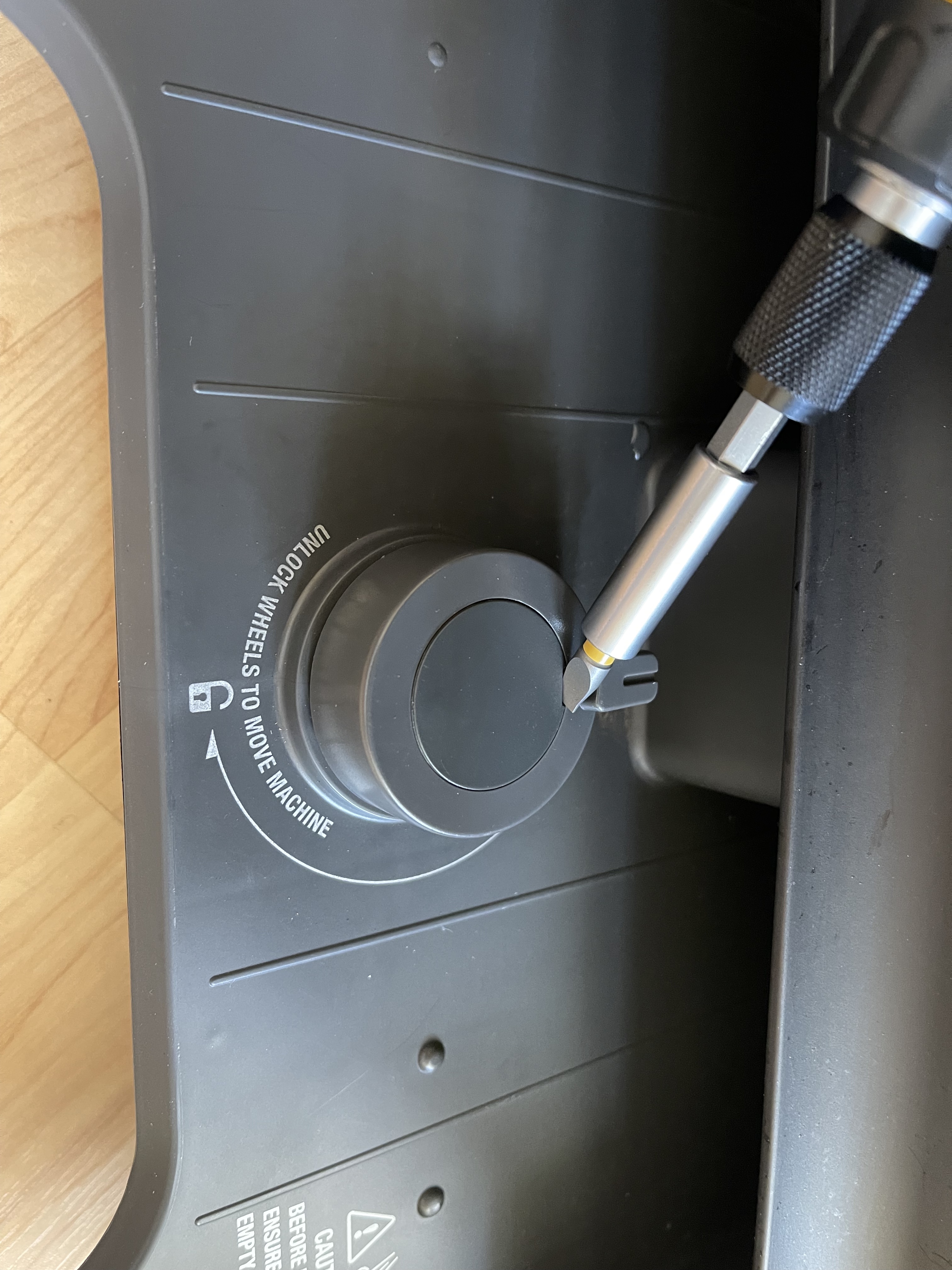
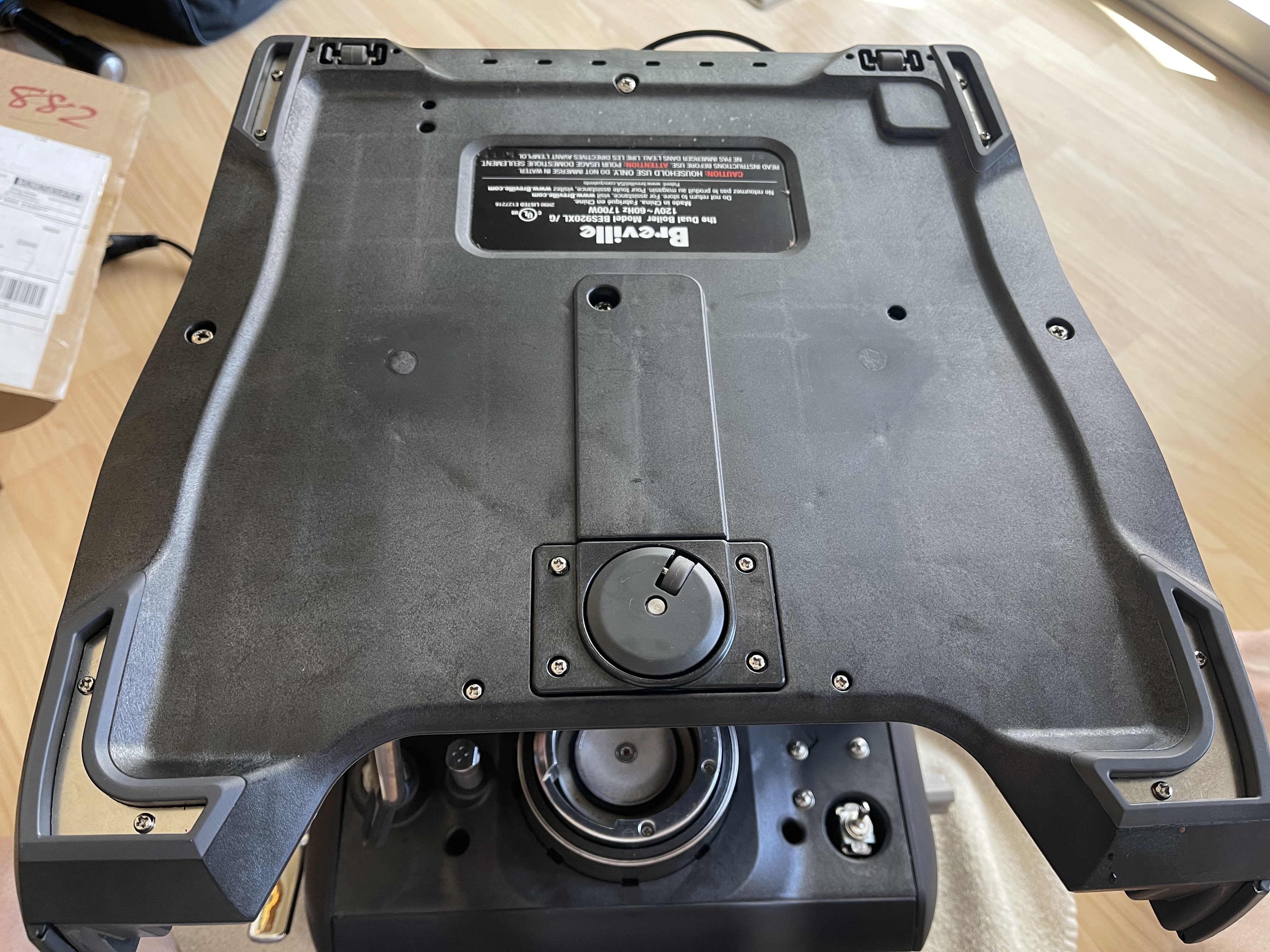
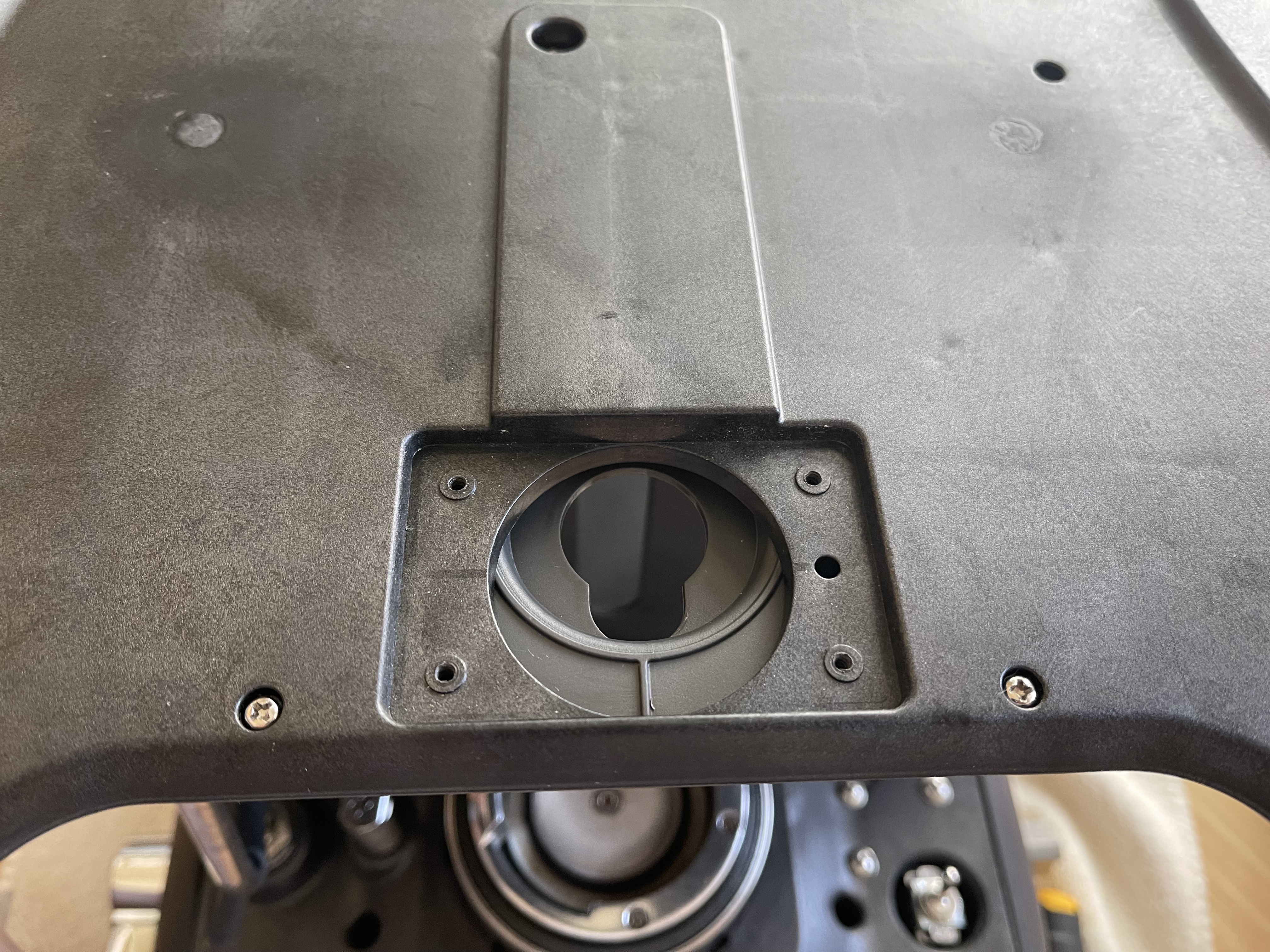
Starting out the conversion with removing the cover that allows access to the screw to detach the top part of the wheel to the bottom part of the wheel.
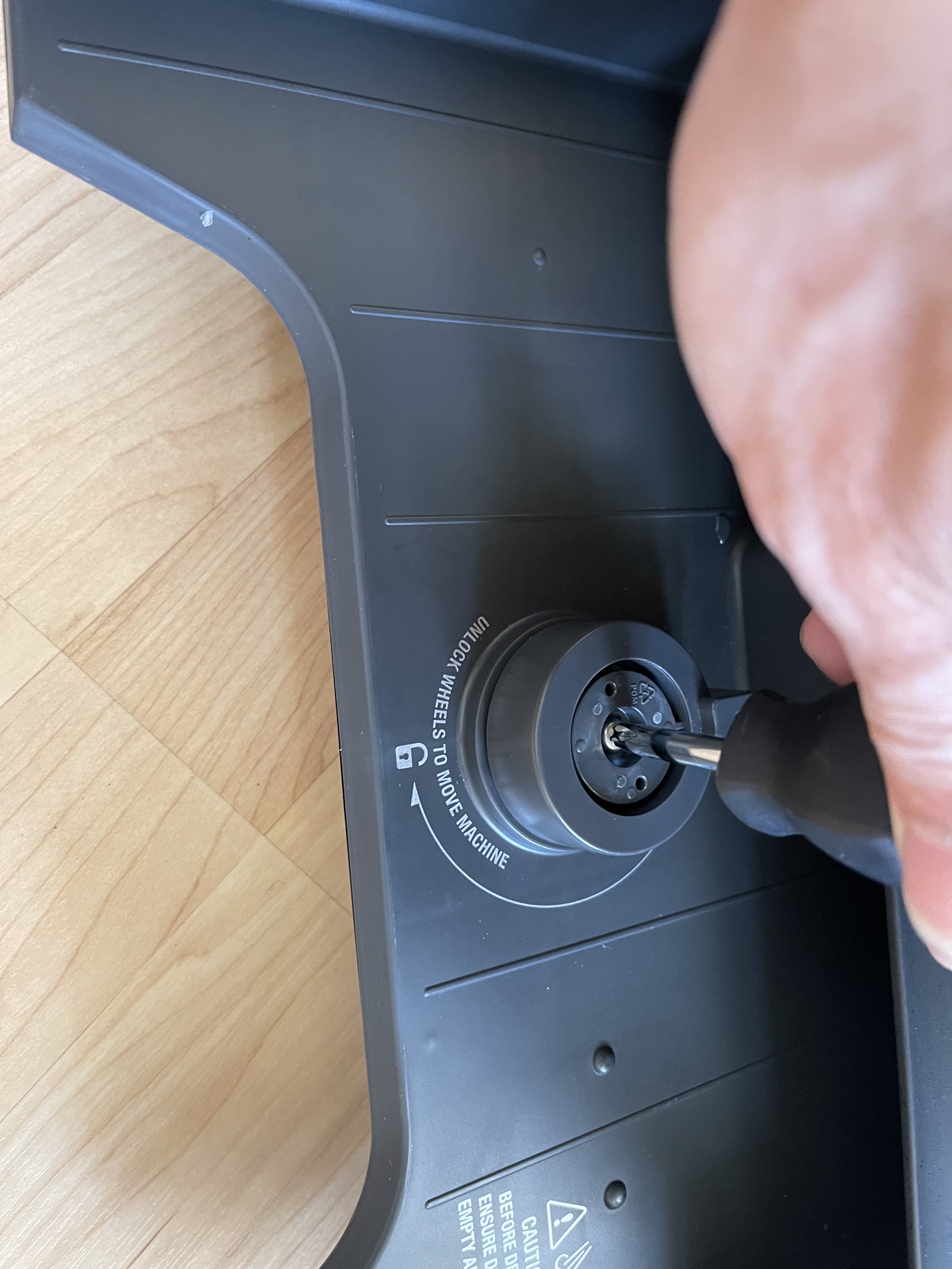
Removing the cover that allows access to the screw to detach the top part of the wheel to the bottom part of the wheel.
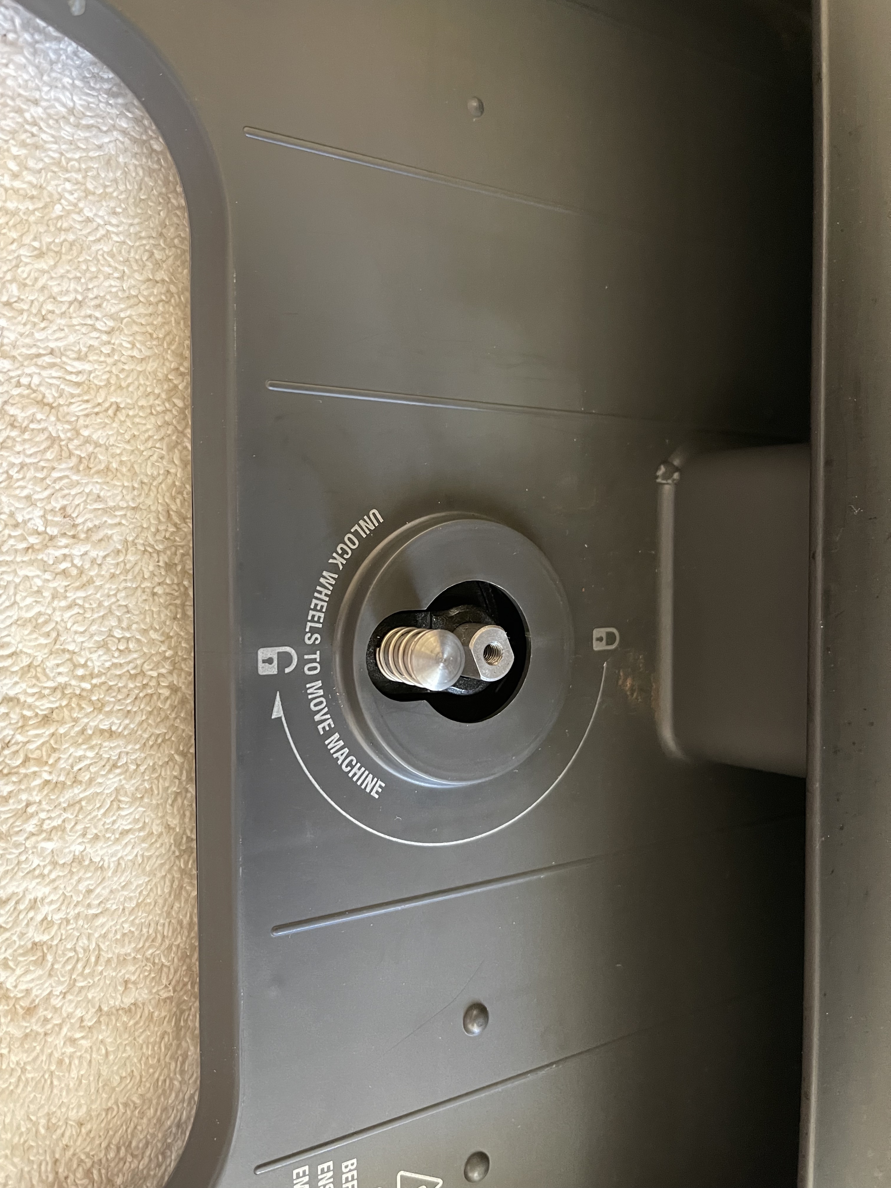
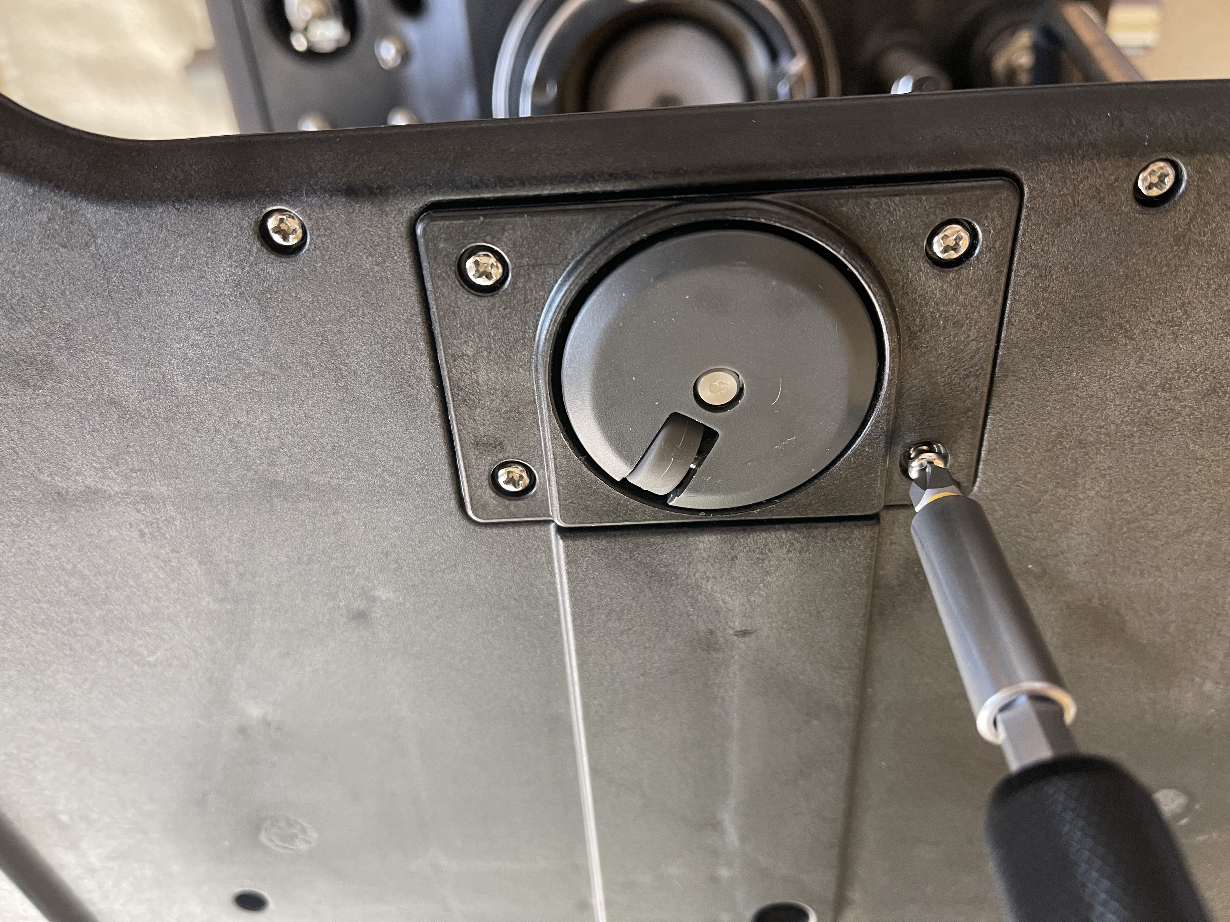
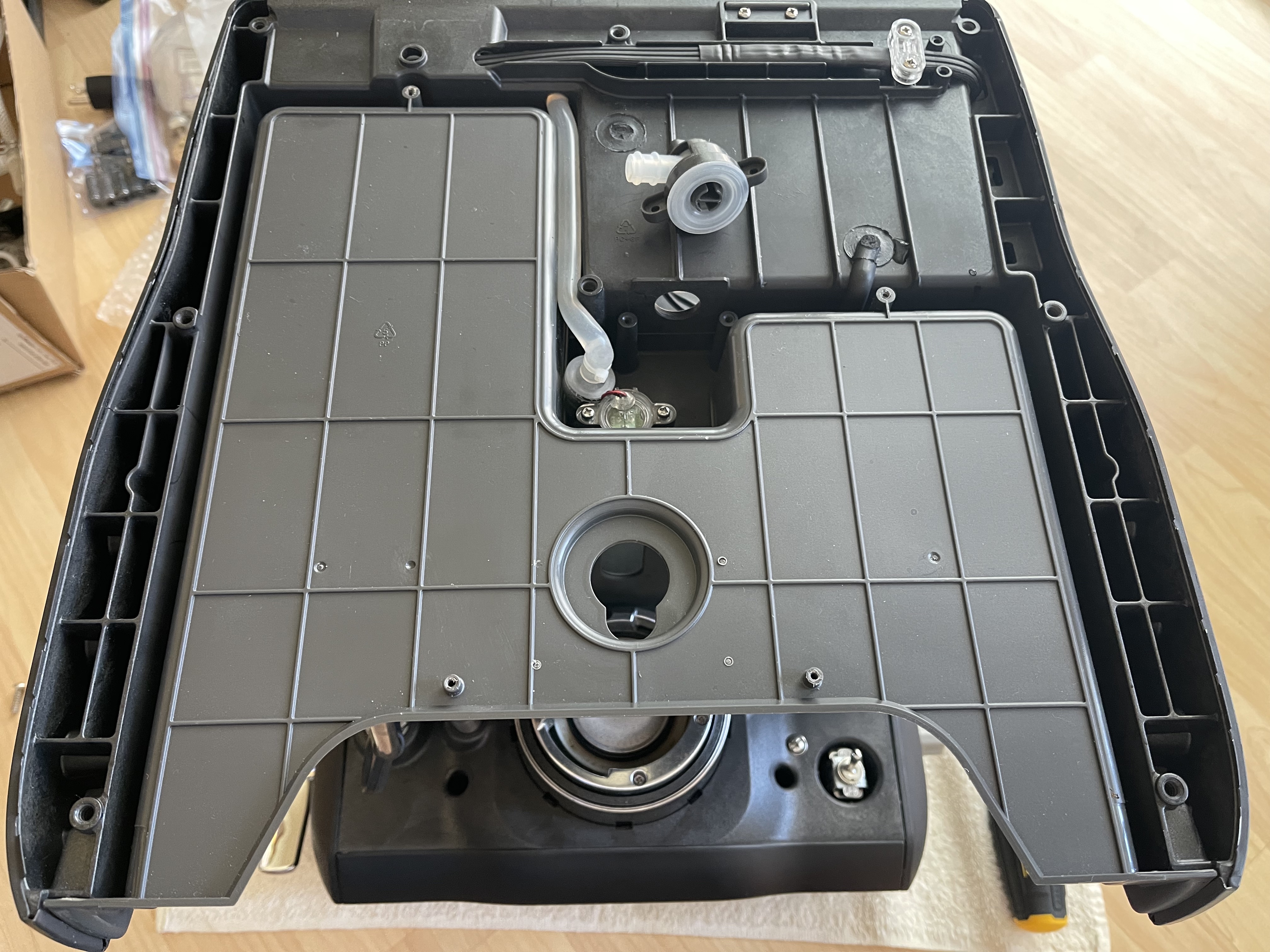
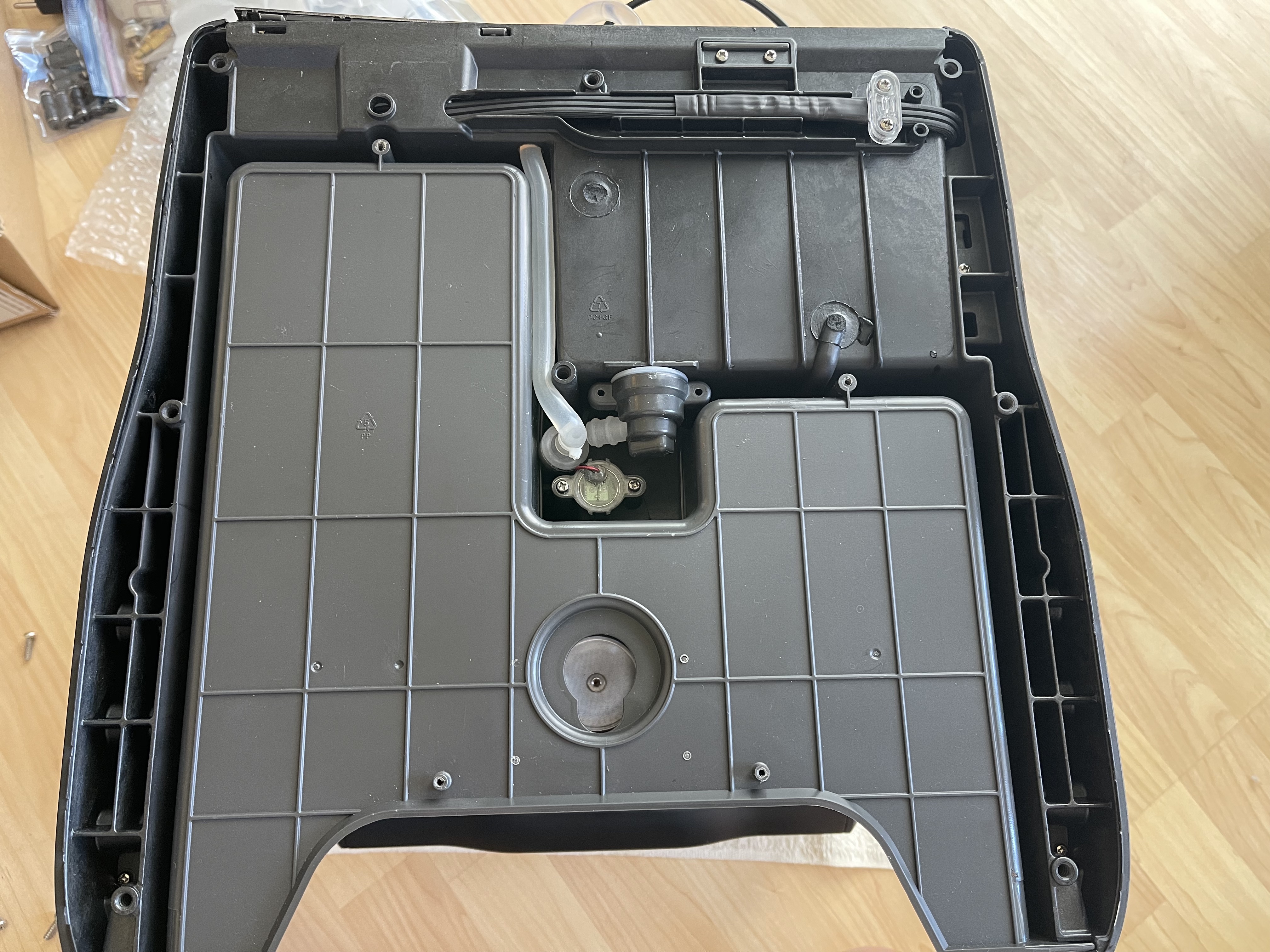
Removing these screws to take the wheel assembly completely off of the base.
There’s a good amount of screws in different length and sizes securing the base to the body of the machine.
This picture shows the water tank’s receiver being detached from the machine’s body.
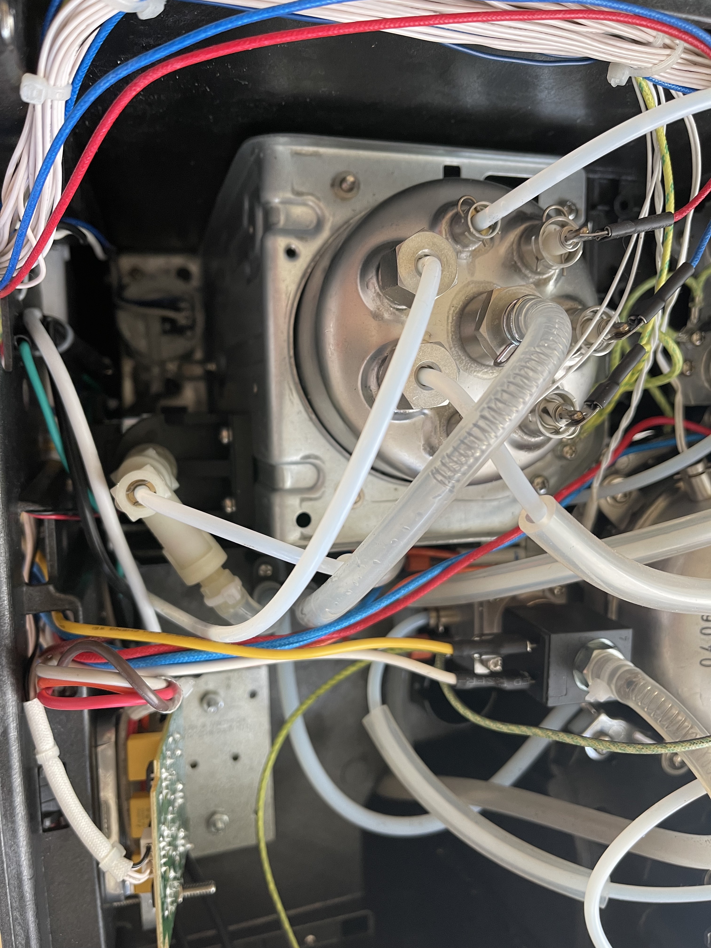
With the base completely off, I was able to reroute the water inlet from the water tank’s receiver and installed a tube which would be connected to the external Brita water container.
Here is a close look of the new tube connected to the air valve.
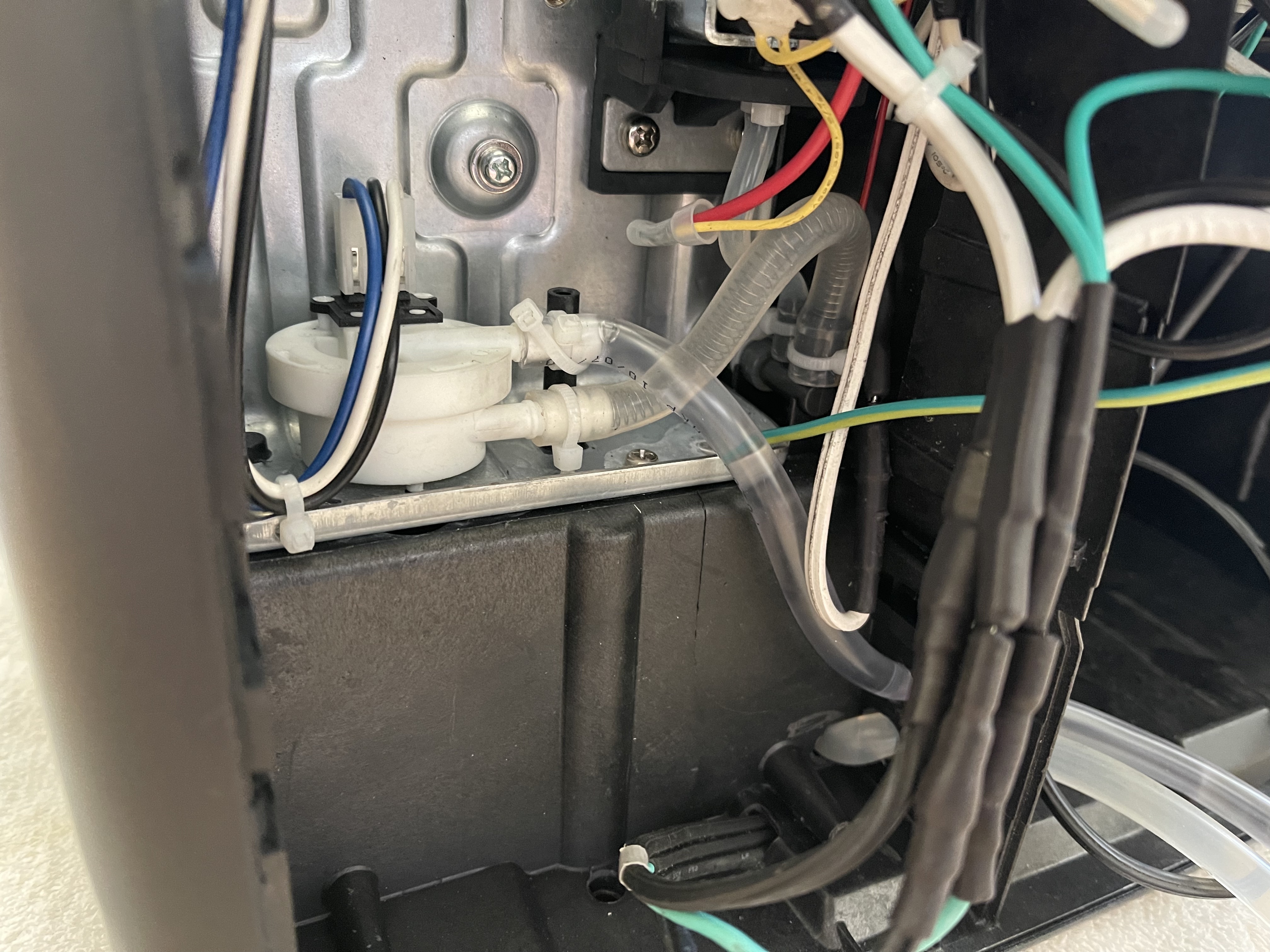
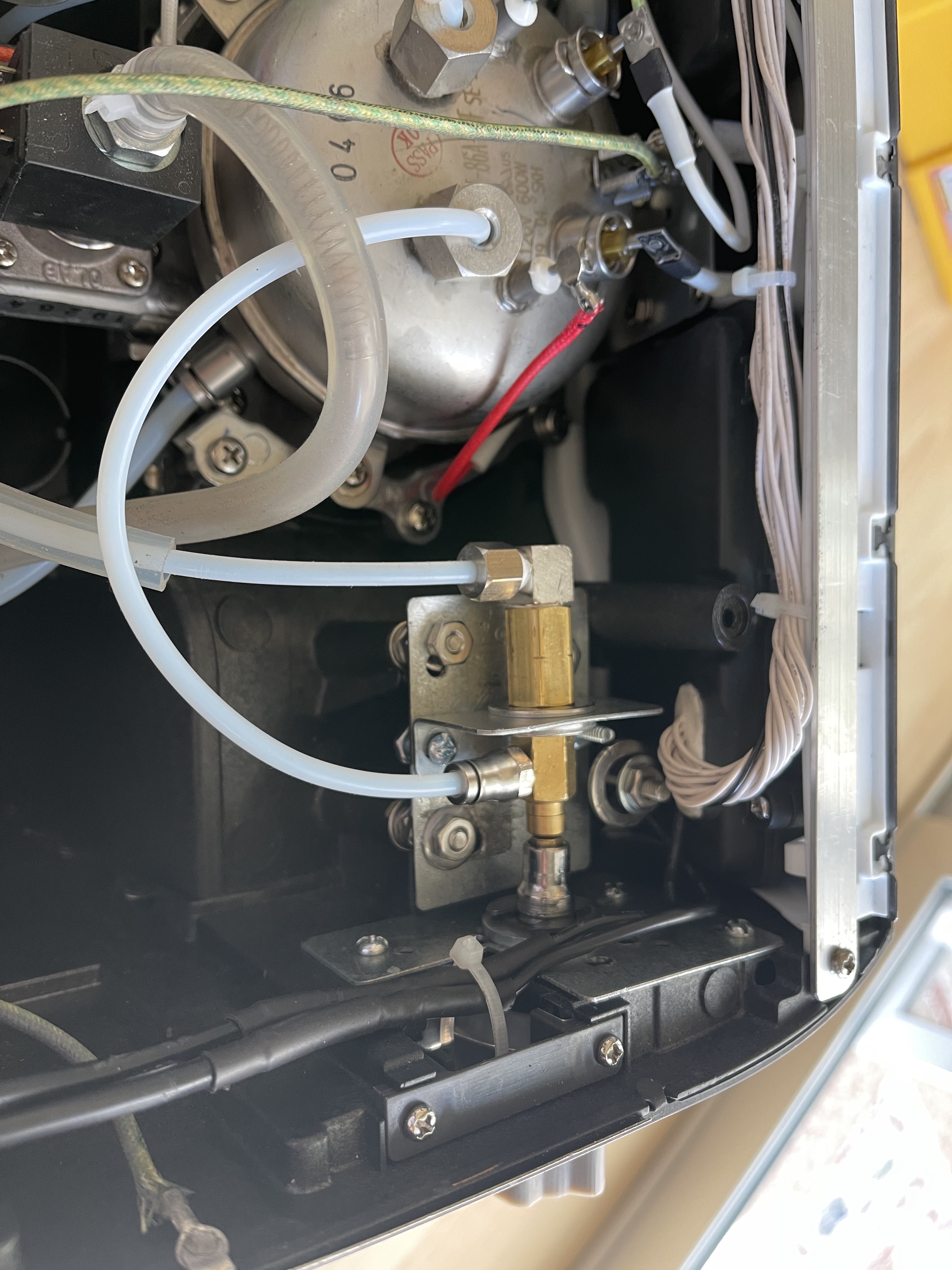
Here is the other side of the water inlet. It is split: one is to feed water to the steam Ulka pump, the other is plugged into the water valve of the brew pump. After taking out the brew Ulka pump, I ran a new tube which would become the new water feed into the rotary pump.
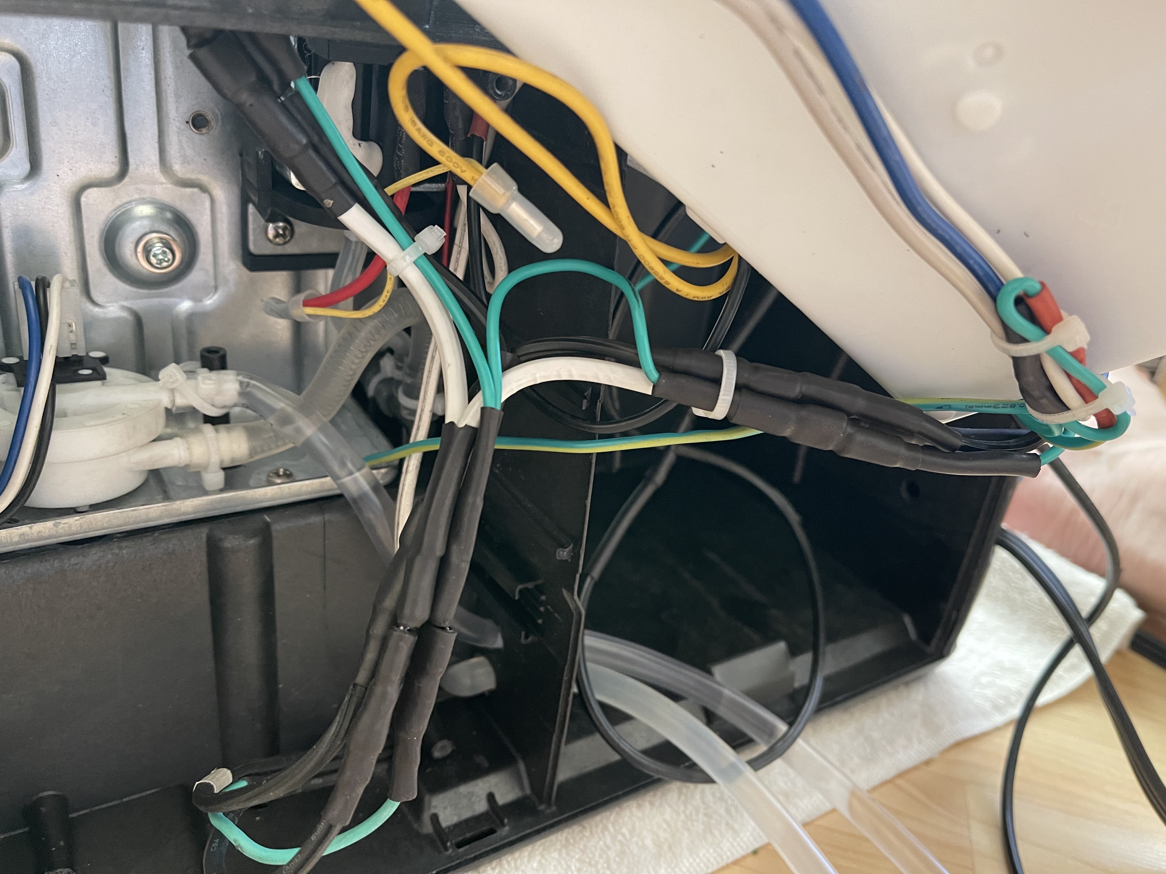
At the same time, I rebuilt the main power cable to allow for 3 Y connectors to be plugged in (ground, hot, and neutral). One end of the Y is going into the PCB board to provide power to it. The other end of the connector is to go to the solid state relay, then to the rotary pump.
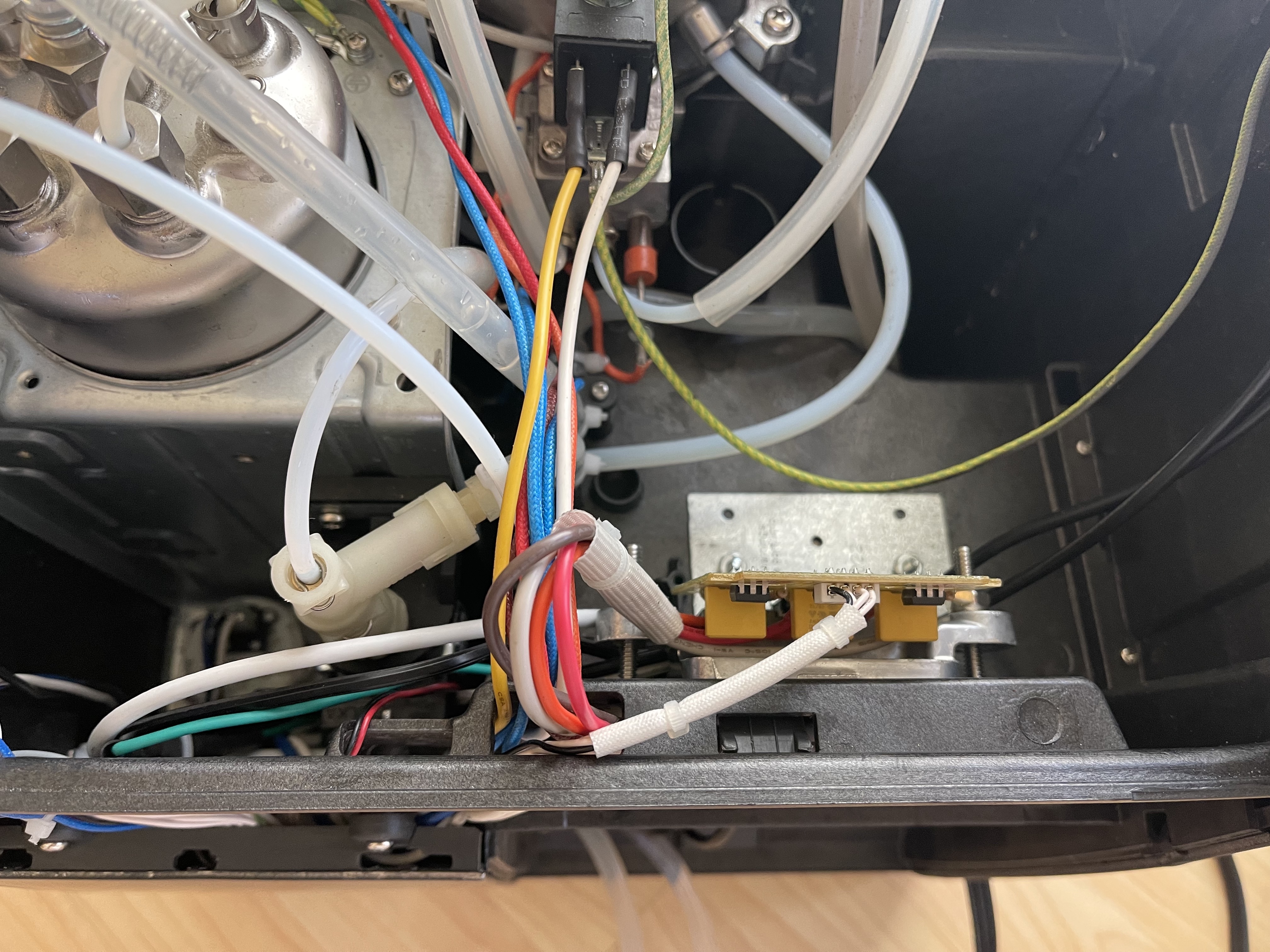
I extended the hot wire that was going to the brew Ulka pump and connected it to the solid state relay.
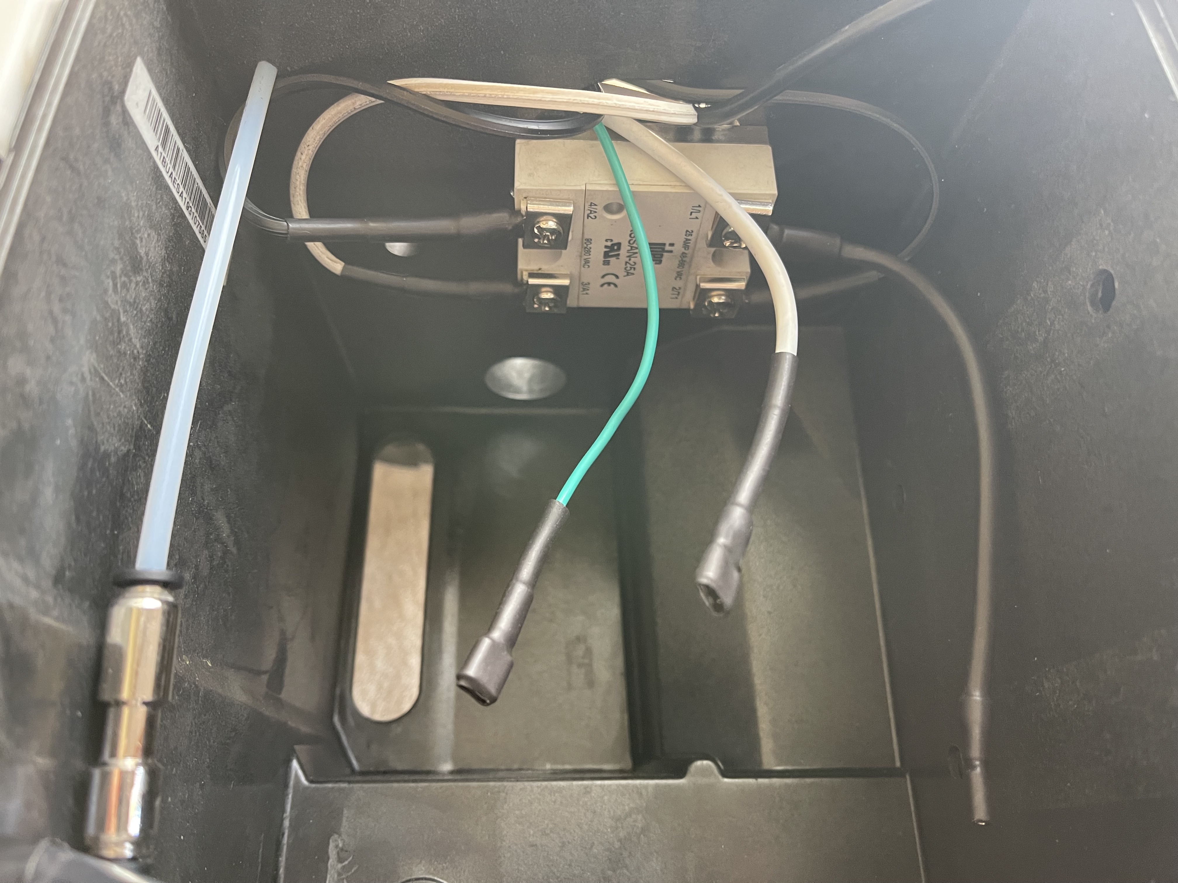
On the left side of the solid state relay, the hot (black) wire is the extension from the PCB board which provides power to the brew Ulka pump. On the right side of the solid state relay, a hot wire from the Y connector is connected to the T (terminal) pole, and a hot wire is plugged into the L (load) pole to the rotary pump, seen here are also the ground and neutral wires from the Y connector split off of the main power cable. Also seen here is the 4mm tube that goes into the exchange tube in the steam boiler. At the end of it is a one-way valve to prevent back flow to the rotary pump.
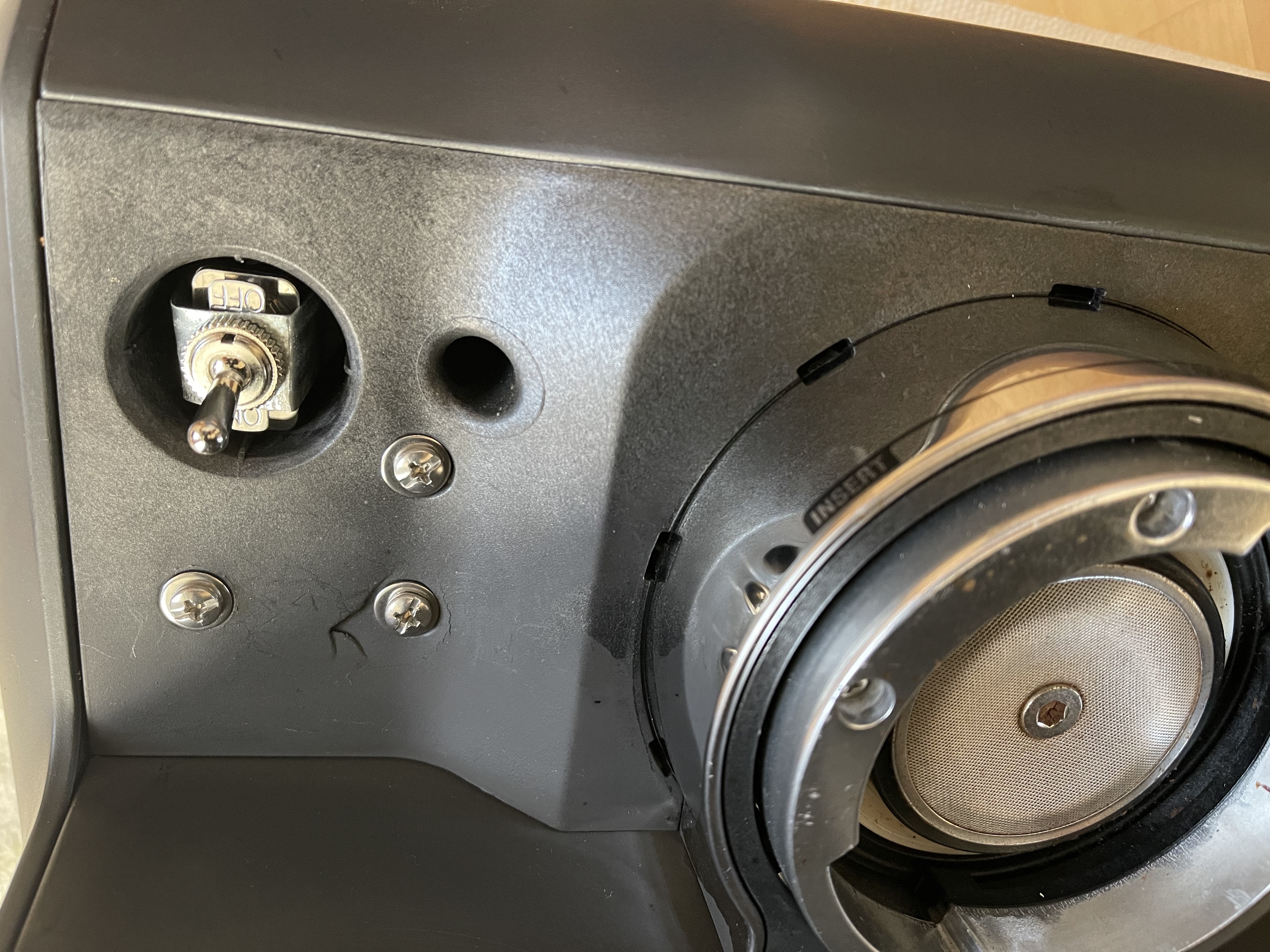
What I did here is I installed a switch that allows me to turn off power to the rotary pump. I put the switch where the Breville tamper goes as I am using a different tamper now which sits on a tamper mat.
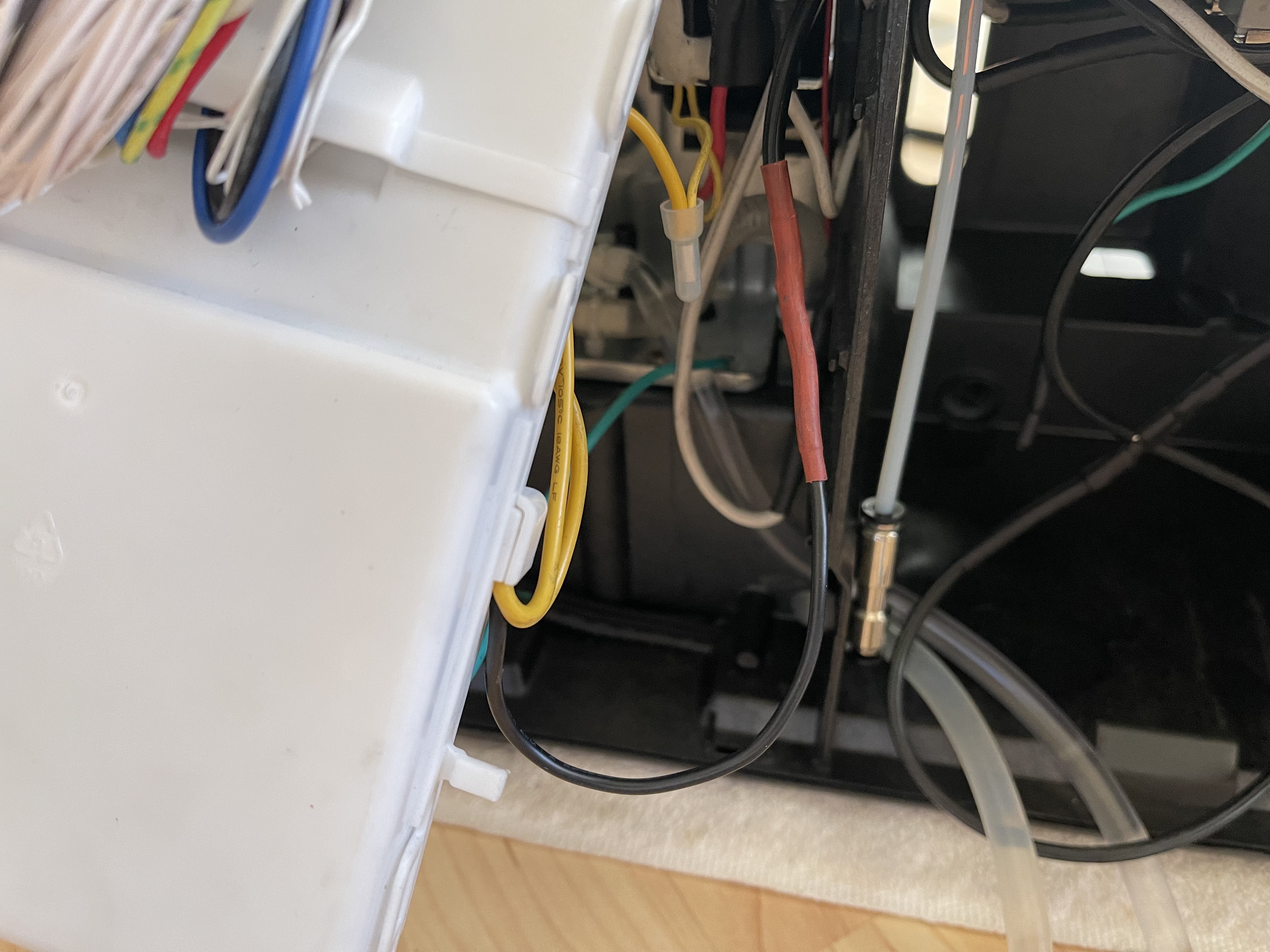
Here you can see the cable run of the switch which allows me to turn off the rotary pump. The switch connects/disconnects the neutral wire.
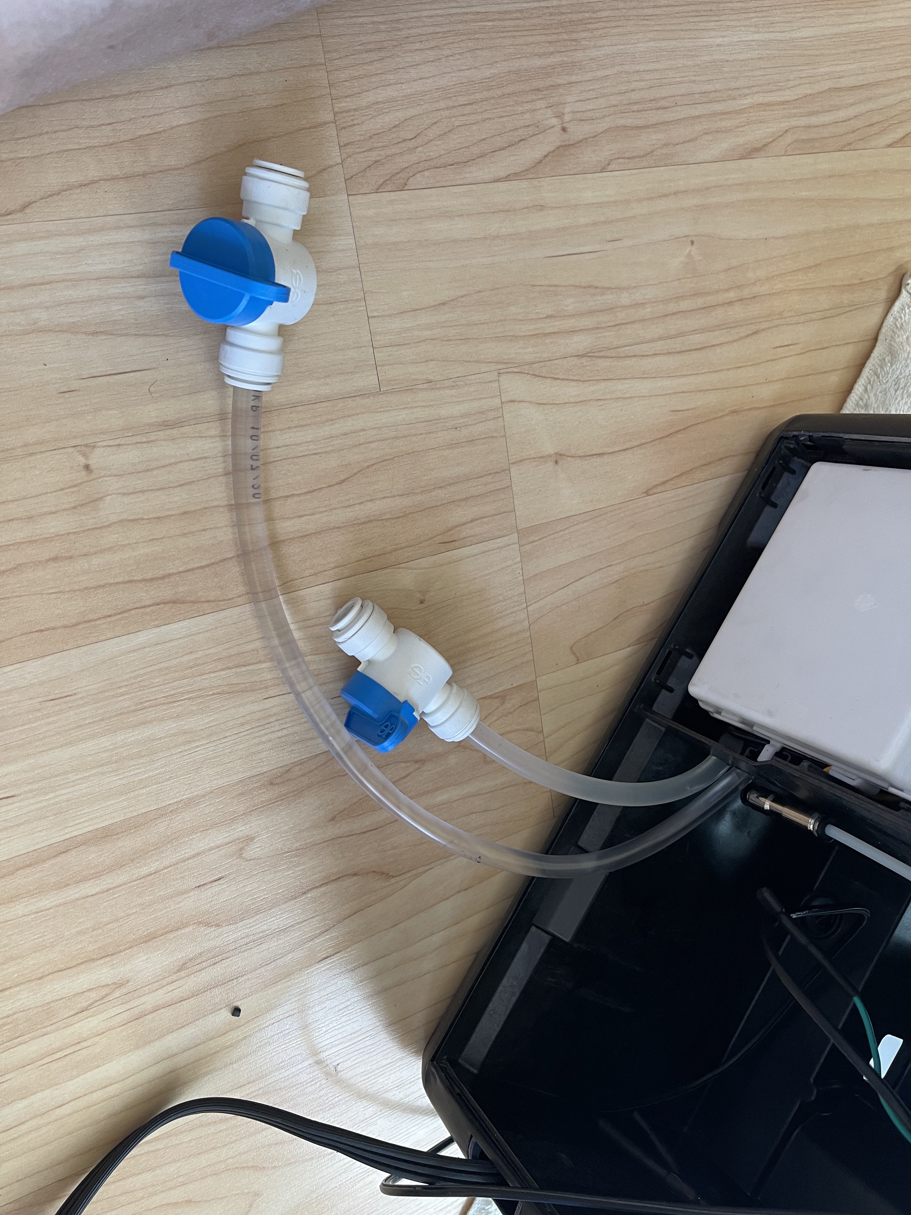
Here you can see a couple of quick disconnects. The short tube is connected to the Brita water containner. The longer tube feeds water to the rotary pump.
Here you can see a couple of quick disconnects. The short tube is connected to the Brita water containner. The longer tube feeds water to the rotary pump.
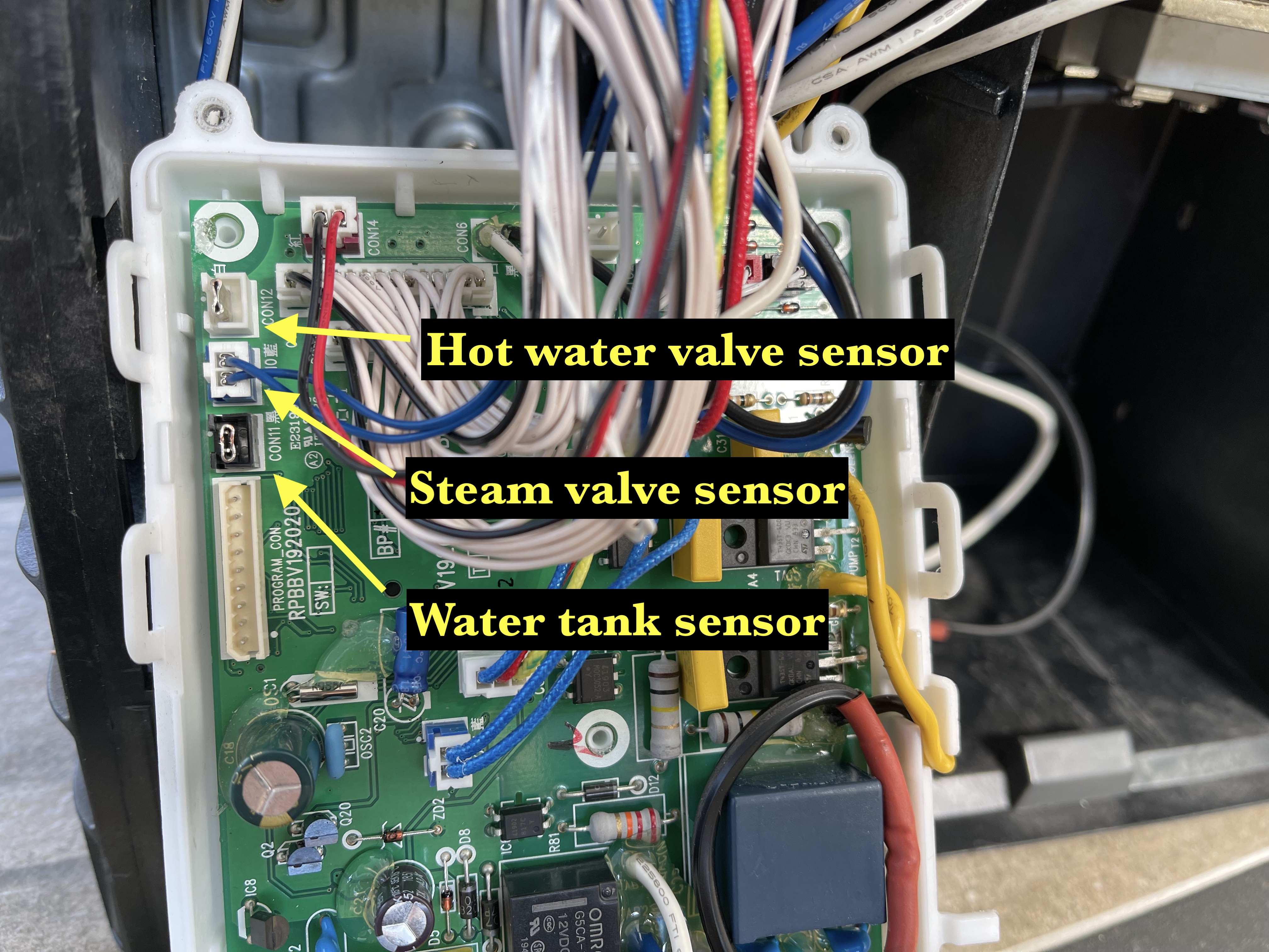
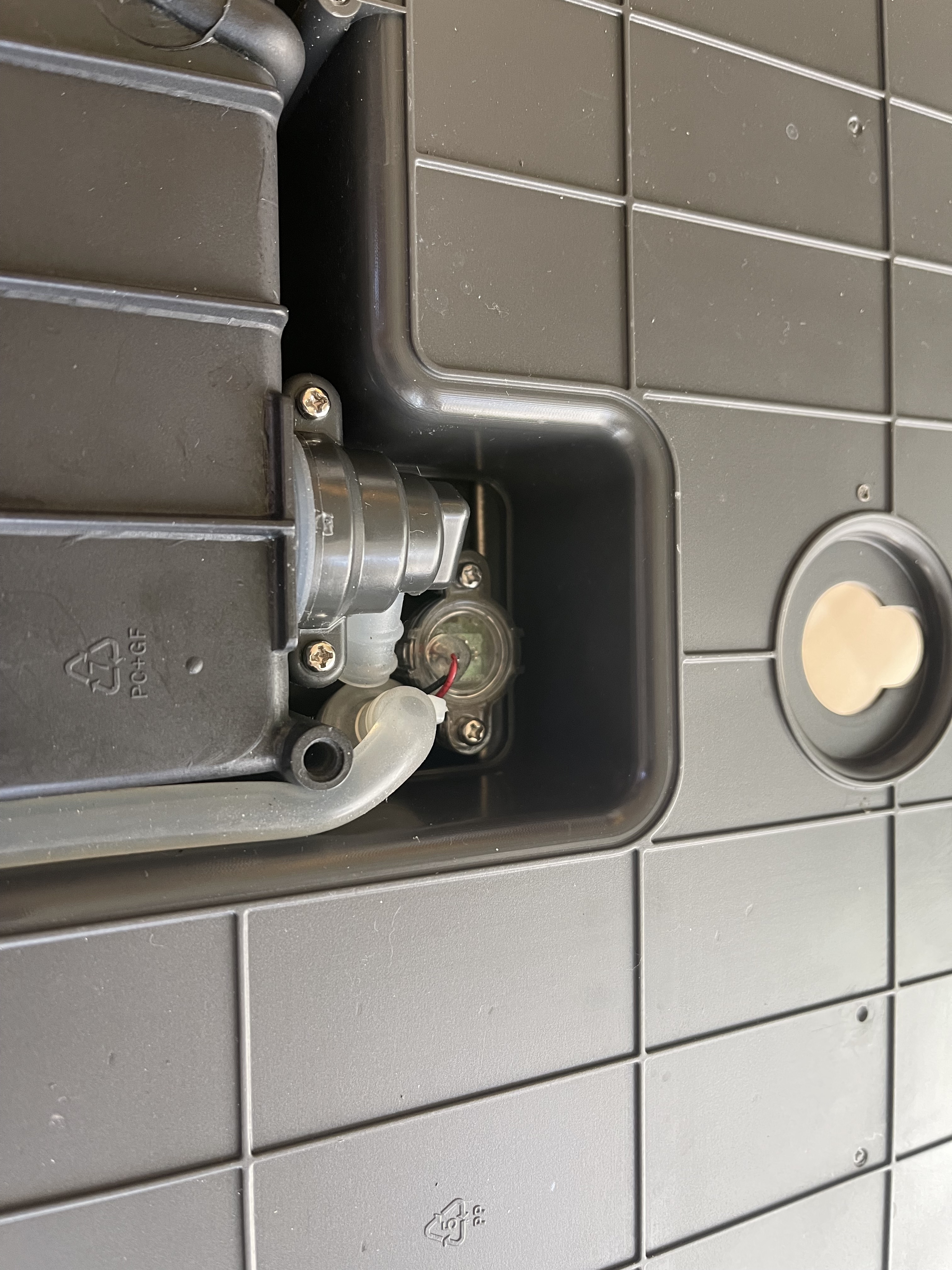
In order to completely remove the original water tank, I added a jumper to the water tank sensor to make the controller board think that the water tank is present and full.
 Another look of the new location for the heating element PCB board. I’ll add an additional heatsink in the near future. You can see here a piece of metal plate, on the other side of it is the solid state relay. I was. originally thinking of putting the pump where the original water tank is, but I changed my mind and decided to keep the rotary pump in a wooden box instead, additional noise reduction :)
Just a couple of additional quick disconnects to prevent water leakage when detaching the rotary pump from the machine.
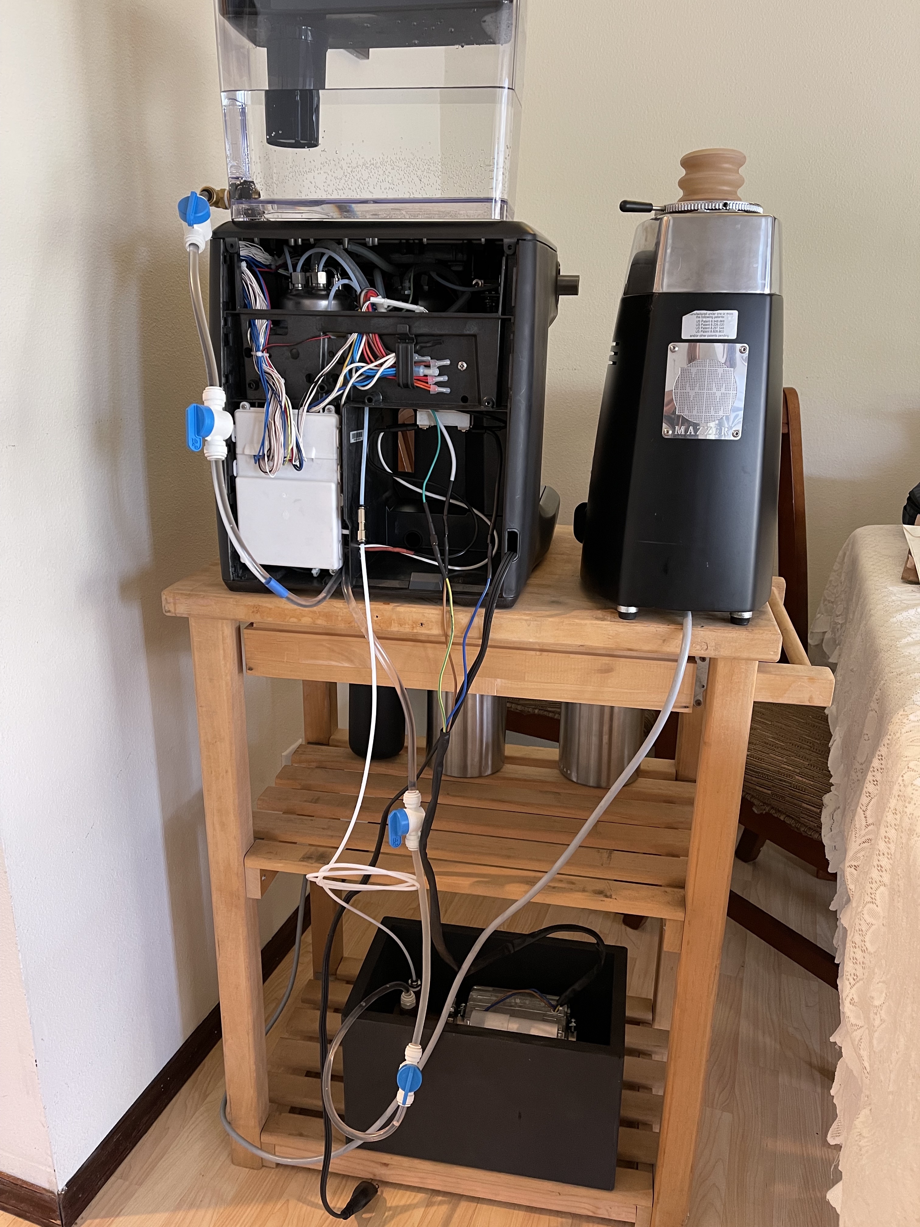
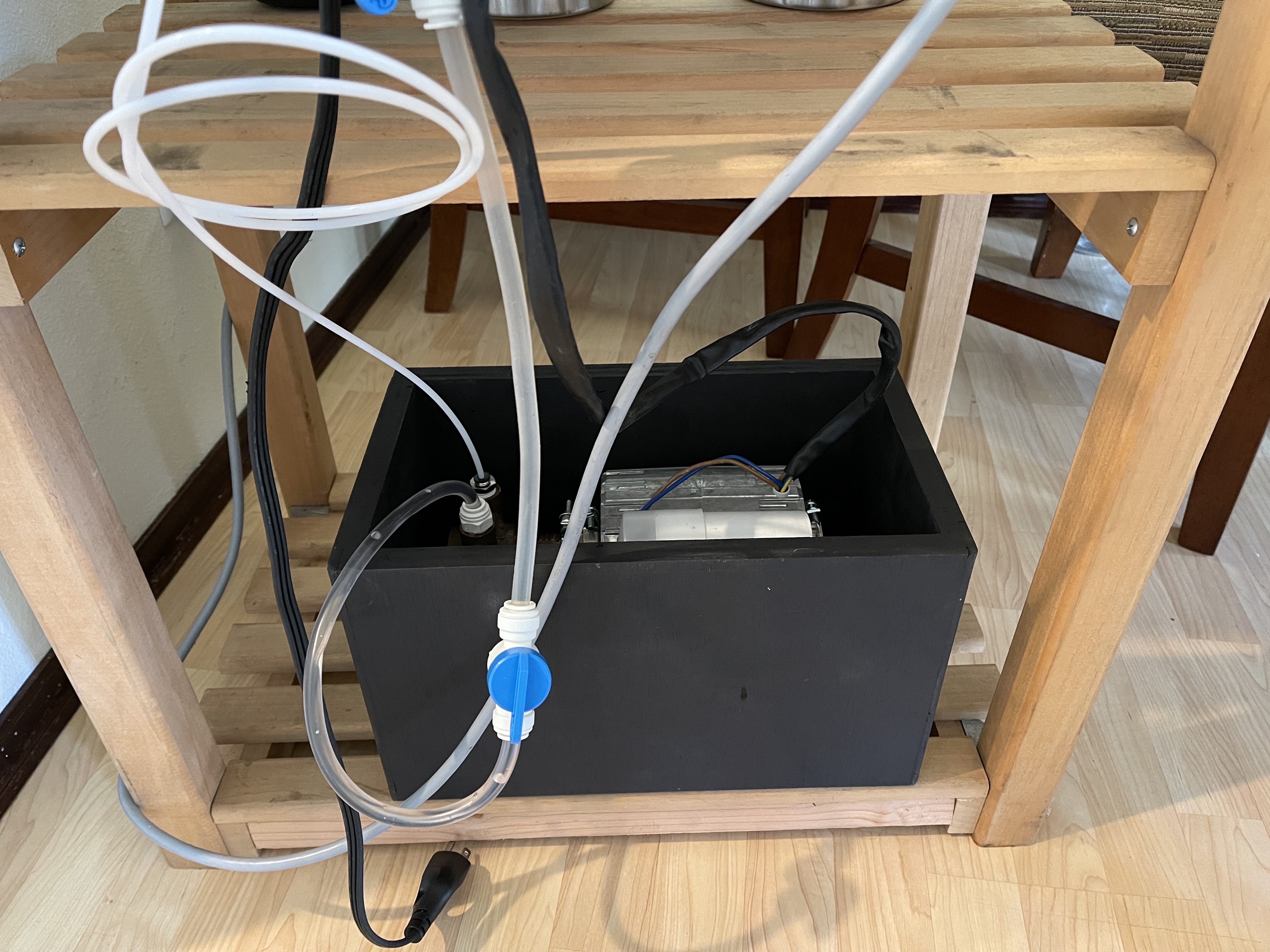
Here is the final setup of the rotary pump conversion. With this setup, water is fed into both the steam boiler pump and brew rotary pump from the Brita water container. This also allows for water line plumb-in in the future by moving the current tube to the Brita to the house water line.
Accurate as of 27 June 2021